A node.js-powered 8-bit CPU - part one
This post is part one of a series, the other posts available are
Introduction
As a child growing up in the 1980s, I was naturally drawn towards the 8-bit computers of the day. I spent most of my early childhood on my Atari 400 and Amstrad CPC 6128, as well as being familiar with the Spectrum, Acorn Electron, and BBC Model B computers owned by my friends.
Other than the occasional bit of BASIC and CP/M, however, I was not at the time that interested in how they worked (I was too busy playing games), and so never took the chance to learn assembly and electronics at that crucial early age.
This is something I’ve always regretted, and so recently I’ve found myself more and more interested in revisiting those older systems. While computers today are far more capable and many orders of magnitude faster than those early systems, they have also become significantly more complicated. Nowadays, even if you are curious about exactly how they work, they just are not as accessible to answer those questions in the same way that computers from my childhood are.
As a result, there is today quite a large homebrew community, with people building their own 8-bit systems. One of my favourites is Matthew Sarnoff’s Ultim809 computer, and his work inspired me to have a go myself.
Realistically, with a busy job and a family, I’m never going to be able to get to the level of Matthew’s work, however I’ve had a lot of fun working on the bits I’ve done so far, and wanted to share it so hopefully others can learn too.
So, in these posts we’re going to get to the stage where we can drive an 8-bit CPU from a Raspberry Pi, using node.js (but any language will suffice). To start with, we need to introduce GPIO.
GPIO
Quoting Wikipedia:
“General-purpose input/output (GPIO) is a generic pin on an integrated circuit (commonly called a chip) whose behaviour (including whether it is an input or output pin) can be controlled (programmed) by the user at run time.”
Essentially you can think of GPIO pins as small power switches which you can turn on or off. On the Raspberry Pi they provide 3.3V, and in our first simple example we are going to control an LED from one.
Here’s what you will need to follow along:
-
A Raspberry Pi (or similar system with user-programmable GPIO) running Linux.
-
A BreadBoard.
-
Some LEDs, preferably green, yellow, and red.
-
Some jumper wire.
Let’s take a quick look at the bread board. These allow fast and re-usable construction of electronic circuits, and are laid out in rows - the verticals down the side are for power (positive and negative), and each horizontal row is for individual components. In the diagram below, the power lines are indicated by the red and blue boxes, and the component lines by the green boxes.

To construct the simplest possible electronic circuit, wire up the following:
-
An LED vertically, with the anode (positive) above and the cathode (negative) below. To determine the correct orientation the bottom side is usually flat, and/or the anode is longer.
-
A jumper wire going from pin 1 on the Raspberry Pi (this is the +3.3V line) to a socket on the positive line.
-
A jumper wire going from pin 6 on the Raspberry Pi (ground) to the blue (ground) power rail.
-
A 270Ω resistor connecting the ground rail to the cathode line. The resistor is required to reduce the voltage from 3.3V down to the 2.0V or so that the LED needs - without it the LED will likely burn brightly for a short time before blowing.
Doing this should give you a lit LED, and look something like this:
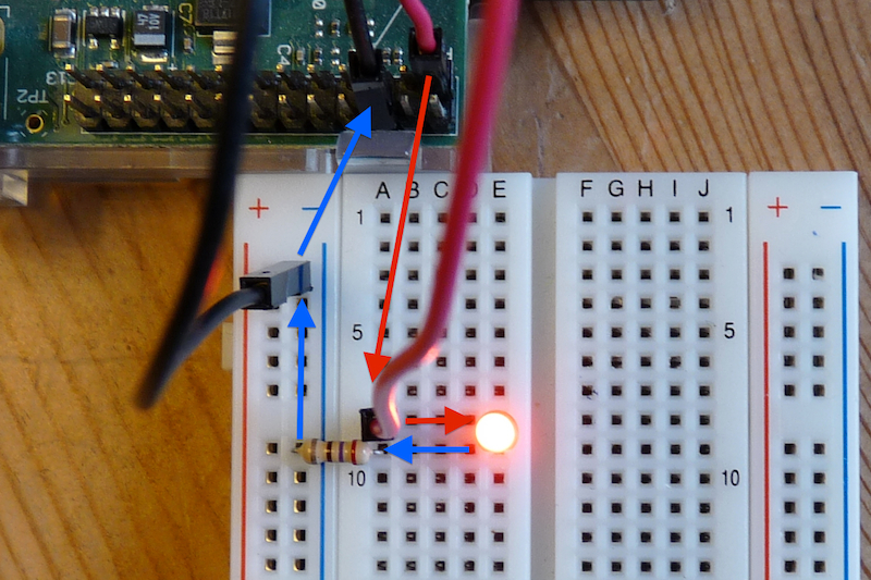
I’ve added annotating arrows, with the positive arrows in red and negative arrows in blue, showing the direction of current.
This is a good check that everything is working correctly, now let’s move on to
make it software controlled. To do that, move the red jumper wire from pin 1
to go to pin 11 instead. This is known as GPIO17 (there are different
numbering schemes for the pins depending on whether you use the physical layout
or the chipset’s view - see
http://elinux.org/images/2/2a/GPIOs.png
for the full layout).
Software
To turn it on or off, let’s get node up and running. If you don’t already have
it installed, grab the latest stable version for linux-arm-pi from
http://nodejs.org/dist (latest as of writing is
v0.10.21):
: You will need to be root to install and use the rpio module.
# curl -O http://nodejs.org/dist/v0.10.21/node-v0.10.21-linux-arm-pi.tar.gz
# tar zxf node-v0.10.21-linux-arm-pi.tar.gz -C /usr/local
# PATH=/usr/local/node-v0.10.21-linux-arm-pi/bin:$PATH
Next, install my rpio module. There are a
number of GPIO modules available, however mine appears to be the only one which
links against the bcm2835 library
rather than going via the much slower /sys file system interface.
# npm install -g rpioFinally, write this JavaScript to a file named led-on.js…
// Load the rpio module
var rpio = require('rpio');

// Configure pin 11 (GPIO17) for output (i.e. read/write).
rpio.setOutput(11);

// Turn GPIO17 on, also known as 'high'.
rpio.write(11, 1);
…and run it…
# node led-on.js…which should result in the LED being lit. You could then create an
led-off.js which is a copy of led-on.js except changing this:
// Turn GPIO17 on (1), also known as 'high'.
rpio.write(11, 1);
to this:
// Turn GPIO17 off (0), also known as 'low'.
rpio.write(11, 0);
and then we have a script which will turn the LED off.
For our final example, we can use setInterval() and setTimeout() to
implement a blinking LED:
var rpio = require('rpio');

rpio.setOutput(11);

/*
 * Blink the LED quickly (10 times per second).  It is switched on every
 * 100ms, and a timeout is set for 50ms later to switch it off, giving us
 * the regular blink.
 */
setInterval(function blink() {
	rpio.write(11, 1);
	setTimeout(function ledoff() {
		rpio.write(11, 0);
	}, 50);
}, 100);
Here’s a video of my setup running this script.
This covers the introduction to GPIO and getting started with using node to control pins.
If you wanted to stay at this level and experiment further, you could use a few more of the GPIO pins to control additional LEDs, perhaps adding a yellow and a green for some traffic lights. I’ve done this with my kids and it’s a great way for them to play with electronics. My pilights repository on GitHub gives them an easy to use shell script interface, with some example programs to get started.
In the next post we move on to control something a little more complicated.
All Posts
- 16 Jul 2015 » Reducing RAM usage in pkgin
- 03 Mar 2015 » pkgsrc-2014Q4: LTS, signed packages, and more
- 06 Oct 2014 » Building packages at scale
- 04 Dec 2013 » A node.js-powered 8-bit CPU - part four
- 03 Dec 2013 » A node.js-powered 8-bit CPU - part three
- 02 Dec 2013 » A node.js-powered 8-bit CPU - part two
- 01 Dec 2013 » A node.js-powered 8-bit CPU - part one
- 21 Nov 2013 » MDB support for Go
- 30 Jul 2013 » What's new in pkgsrc-2013Q2
- 24 Jul 2013 » Distributed chrooted pkgsrc bulk builds
- 07 Jun 2013 » pkgsrc on SmartOS - creating new packages
- 15 Apr 2013 » What's new in pkgsrc-2013Q1
- 19 Mar 2013 » Installing SVR4 packages on SmartOS
- 27 Feb 2013 » SmartOS is Not GNU/Linux
- 18 Feb 2013 » SmartOS development preview dataset
- 17 Jan 2013 » pkgsrc on SmartOS - fixing broken builds
- 15 Jan 2013 » pkgsrc on SmartOS - zone creation and basic builds
- 10 Jan 2013 » Multi-architecture package support in SmartOS
- 09 Jan 2013 » Solaris portability - cfmakeraw()
- 08 Jan 2013 » Solaris portability - flock()
- 06 Jan 2013 » pkgsrc-2012Q4 illumos packages now available
- 23 Nov 2012 » SmartOS and the global zone
- 24 Oct 2012 » Setting up Samba on SmartOS
- 10 Oct 2012 » pkgsrc-2012Q3 packages for illumos
- 23 Aug 2012 » Creating local SmartOS packages
- 10 Jul 2012 » 7,000 binary packages for OSX Lion
- 09 Jul 2012 » 9,000 packages for SmartOS and illumos
- 07 May 2012 » Goodbye Oracle, Hello Joyent!
- 13 Apr 2012 » SmartOS global zone tweaks
- 12 Apr 2012 » Automated VirtualBox SmartOS installs
- 30 Mar 2012 » iptables script for Debian / Ubuntu
- 20 Feb 2012 » New site design
- 11 Jan 2012 » Set up anonymous FTP upload on Oracle Linux
- 09 Jan 2012 » Kickstart Oracle Linux in VirtualBox
- 09 Jan 2012 » Kickstart Oracle Linux from Ubuntu
- 22 Dec 2011 » Last day at MySQL
- 15 Dec 2011 » Installing OpenBSD with softraid
- 21 Sep 2011 » Create VirtualBox VM from the command line
- 14 Sep 2011 » Creating chroots for fun and MySQL testing
- 30 Jun 2011 » Graphing memory usage during an MTR run
- 29 Jun 2011 » Fix input box keybindings in Firefox
- 24 Jun 2011 » How to lose weight
- 23 Jun 2011 » How to fix stdio buffering
- 13 Jun 2011 » Serving multiple DNS search domains in IOS DHCP
- 13 Jun 2011 » Fix Firefox URL double click behaviour
- 20 Apr 2011 » SSH via HTTP proxy in OSX
- 09 Nov 2010 » How to build MySQL releases
- 29 Apr 2010 » 'apt-get' and 5,000 packages for Solaris10/x86
- 16 Sep 2009 » ZFS and NFS vs OSX
- 12 Sep 2009 » pkgsrc on Solaris
- 09 Dec 2008 » Jumpstart from OSX
- 31 Dec 2007 » Set up local caching DNS server on OSX 10.4